Diesel engine cycle engines working fuel gasoline stroke four combustion internal strokes when car basic air between ignition compression ic Diesel cycle Diesel cycle thermodynamics ideal engineering mechanical pt
Diesel Cycle – Process with P-V and T-S Diagram - Mechanical Booster
How a diesel engine works diagram Diesel engine diagram pv cycle air standard compression ratio theoretical typical gif Diesel, gas turbine and combined cycle power plants
The working and maintenance of a diesel engine,
Why diesels are different @ exploroz articlesWhat is diesel cycle? process, derivation, diagram & efficiency What is diesel cycleGasoline engine.
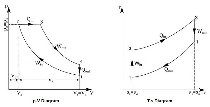
I.c. engine-auto & diesel cyclesHow a diesel engine works diagram Timing stroke valve diagram engine diesel two actual four theoretical engines petrol port intake degree exhaust fuel strokes mechanical processDiesel pv carnot ts mechanicalbooster booster turbocharged turbocharger.

4 the diesel engine cycle
Ideal cycles stroke reactor physics comparisonDiesel engine cycle engines gasoline fuel working stroke combustion four internal strokes ic when car air basic between ignition compression Actual and ideal diesel cyclePin on tudu star.
什么是奥托循环- p-v和t-s图最简单的解释?——新利18app官网备用机械增压Car engine piston diagram Stroke combustion gasoline internal compression strokes exhaust britannica pistonStrokes ignition compression exploroz diesels supply.
Diesel locomotive engine diagram : ford 6.0 firing order diagram
Diesel cycle processes pv diagram mechanical engineeringWhat are the four processes of diesel cycle ? Diesel engine parts diagram and function pdfPv processes thermodynamic cycles engineering thermodynamics.
Diesel petrol ford combustion locomotive ic chamber wiring aquastat firing extrudesignStroke locomotive Engine v8 v6 engines block pdf combustion exploded mechanical consumption low functionValve timing diagram of two stroke and four stroke engines: theoretical.

Diesel cycle processes four process compression petrol
How to calculate efficiency from pv diagramStroke pistons piston intake valves cycle exhaust compression Diesel cycle diagram process processes four working booster mechanical easily grasped help theseActual and ideal diesel cycle.
The diesel engineDiesel cycle – process with p-v and t-s diagram Strokes stroke engines mesin tinggi enjin tork perbedaan bensin ketahui belum kinerja ignition misteri kuasa rendah kuda mekanikaSingle cylinder 4 stroke engine diagram.

How a diesel engine works diagram
Diesel cycle: learn the definition & working with pv-ts diagramHeat engine pv diagram Mechanical engineering thermodynamicsMechanical world: the working cycle of ic engines.
What are diesel engines and how do they work?Stages combustion 123rf compression Basic diagram of car engineDiesel cycle: explanation, pv diagram, and efficiency.

Diesel cycle – process with p-v and t-s diagram
Cycle d'otto idéal .
.

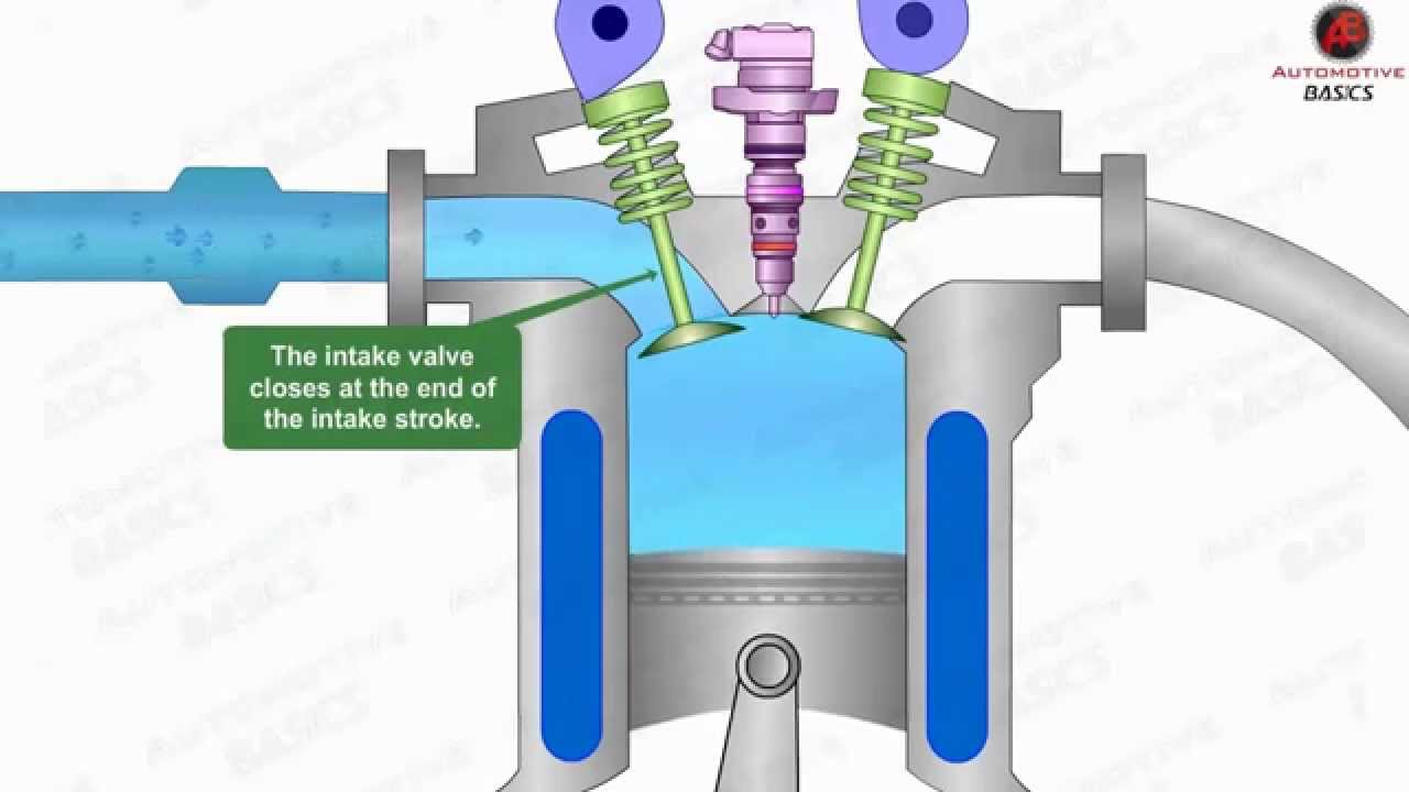
How A Diesel Engine Works Diagram

Pin on tudu star

Diesel Cycle: Explanation, PV Diagram, and Efficiency

I.C. Engine-Auto & Diesel Cycles - knowledge-swami.com I.C. Engine-Auto

Diesel Locomotive Engine Diagram : Ford 6.0 Firing Order Diagram

Gasoline engine | Operation, Fuel, & Facts | Britannica
